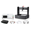
If you have a lot of LEDs and you simply wish to confirm basic color and illumination, a camera-based system may be a good fit. This camera peripheral is connected to the PLT and can be configured with simple PASS criteria so that you can confirm a correct LED pattern on your board.
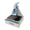
Integration of a switch that is closed when the fixture is closed. This can be used for safety features: don't supply power until the fixture is closed. You can also use this to speed up cycle times by triggering events based on the closure of the fixture clamp.
The STEP file of the device is used to build the Pogo Pin Cassette without interference with the various fixture components. If you have a sample board but not the STEP file, we can recreate it for you manually.
With test points on your Ethernet lines, pogo pins are routed to an Ethernet-enabled device in the Pogo Pin Cassette to test your device's Ethernet communication paths. Speeds may be limited by the use of pogo pin test probes.
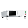
Integration of 6.5-digit digital multimeter into Pogo Pin Cassette. This brings the measurement hardware even closer to your device for improved accuracy.